")
")
Odometry, GPS
- Details
- AlexanderG
- Instructions
- Hits: 16069
Note: Use the WIKI for latest informationen!

Using odomety you can calculate the robot's speed and the short-term position of the robot. This works by counting the rotations of left and right wheel.
Examples:
Ardumower-Motor
Wiring of motor encoders:
green-----GND
brown----VCC
blue-----odometry1
purple---odometry2
Signal of odometry encoders

Do-It-Yourself encoders


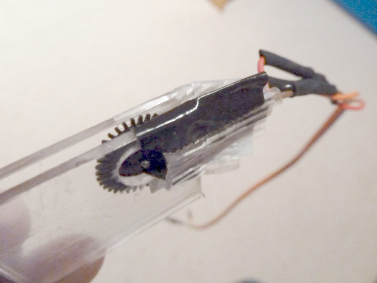
Ambrogio L50 (left): An encoder wheel of a computer mouse is glued to a slice. The screw of the wheel shaft is unscrewed, and the slice is added. Embedded in two Plexiglas pieces is a photo diode and photo transistor of a light barrier (e.g. LTH 301).
Tianchen TC-G158 (right): A light barrier (e.g. LTH 301) is interrupted by a gear-weheel of the motor shaft.
Circuit
VCC           pinArduino
 +--13 KOhm----+-------Collector  Emitter---GND
 +--380 Ohm------------Anode      Kathode---GND
Example plot of odometry sensors

After a time, the odometry's error accumulates, and the course (Degree) and position (x/y) are getting unprecise - the course can be corrected by a compass sensor, the position by GPS.
Fusion of sensor values:
1. Calculation of short-time position by Odometry and Compass
2. Calculation of long-term position via GPS
A Kalman filter can be used to fusion all sensor values.
GPS


By the help of a GPS receiver (e.g. GY-NEO6MV2, ublox 6m), the long-term position can be calculated. Therefore, the GPS position values are averaged.
Wiring:
GPS TX (3.3V compatible) -- Arduino RX
 GPS RX (3.3V compatible) -- Arduino TX
 GPS VCC -- Arduino VCC 5V
 GPS GND -- Arduino GND
Visualization of GPS data
GPS data (course, speed, position etc.) can be plotted by pfodApp:


![]()
Simulation
Here's a simulation of localization using odometry sensors.
Position detection using cross-correlation
![]()
Videos No video yet (odometry is currently under development)