")
")
- Details
- Markus
- Instructions
- Hits: 15624
Note: Use the WIKI for latest informationen!
The robot requires a clock, so that it can start mowing automatically at certain time intervals (timer).
A realtime clock (RTC) returns current time (minute, hour) and date (day of week, day, month, year) - by the help of a battery the time continues to run even if the robot mower is switched off.
Example: DS1307

Wiring
The RTC module is connected on the I2C bus of the Arduino Mega (in parallel with any other I2C modules).
DS1307 Module SDA — Arduino SDA Pin
DS1307 Module SCL — Arduino SCL Pin
DS1307 Module VCC (+5V) — Arduino VCC (+5V)
DS1307 Module GND — Arduino GND
Note
If you experience communication problems when using multiple I2C modules on one I2C bus, it is recommended to reduce the length of the cables.
Timer
On the robot, several timers can be programmed (via Android pfodApp). For each timer, you can define a time interval and the desired days.
Example:
Timer 1: 08:00 - 13:00 Monday, Thuesday, Wednesday
Timer 2: 14:00 - 16:00 every day
Timer 3: off
Timer 4: off
- Details
- Markus
- Instructions
- Hits: 17927
Note: Use the WIKI for latest informationen!
As a motivation, here you can see some examples for a commercial chassis that you could use for this project (Tianchen, Denna, Supoman, Ambrogio, FriendlyRobotics, Gardena, Husqvarna, Bosch, Viking, ... ). You can find chassis of older robots on eBay. The robot's original electronics can be damaged as you'll use the new 'Ardumower' electronics for it.
FriendlyRobotics Robomow RL350


Wheel: 2 x motors 24V (brushed)
Mower: 3 x motors 24V, 5800rpm (brushed)
Size: 89x66x32cm (LBH)
Denna L600


Wheel: 2 x motors 24V, 22W (brushed)
Mower: 1 x motor 24V, 3200rpm (brushed)
Size: 62x49x30cm (LBH)
Ambrogio L50


Wheels: 2 x motors 24V (brushed)
Mower: 1 x motor 24V, 120W, 4000rpm (brushed)
Size: 41x33x20cm (LBH)
Special feature: 4-wheel-drive (4WD) via belts
Supoman SPM08-320
Wheels: 2 x Motor 24V, 25W (brushed)
Mower: 3 x Motor 24V, 130W, 6000rpm (brushed)
Size: 59x58x23cm (LBH)
Tianchen TC-G158


Wheels: 2 x motors 24V (brushed)
Mower: 2 x motors 24V, 82W, 5000rpm (brushed)
Size: 56x51x25cm (LBH)
Ideas for an Ardumower-Chassis (in development/planning)


Wheels: 2 x Motor
Mower: 1 x Motor
Size: 64x40x25cm (LBH)
More details on the Ardumower Chassis can be found here.
- Details
- AlexanderG
- Instructions
- Hits: 16508
Note: Use the WIKI for latest informationen!

Using odomety you can calculate the robot's speed and the short-term position of the robot. This works by counting the rotations of left and right wheel.
Examples:
Ardumower-Motor
Wiring of motor encoders:
green-----GND
brown----VCC
blue-----odometry1
purple---odometry2
Signal of odometry encoders

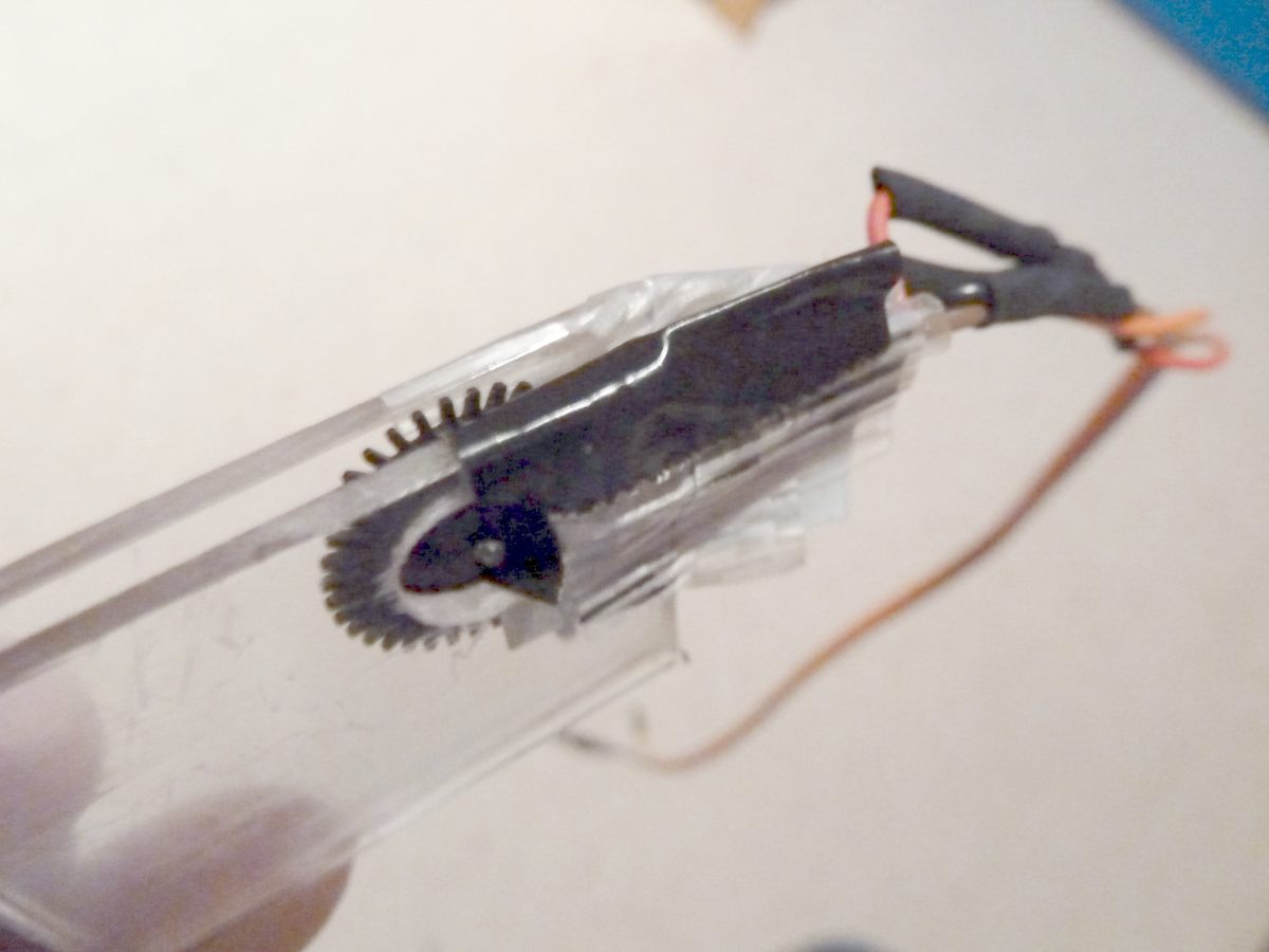
Do-It-Yourself encoders


Ambrogio L50 (left): An encoder wheel of a computer mouse is glued to a slice. The screw of the wheel shaft is unscrewed, and the slice is added. Embedded in two Plexiglas pieces is a photo diode and photo transistor of a light barrier (e.g. LTH 301).
Tianchen TC-G158 (right): A light barrier (e.g. LTH 301) is interrupted by a gear-weheel of the motor shaft.
Circuit
VCC           pinArduino
 +--13 KOhm----+-------Collector  Emitter---GND
 +--380 Ohm------------Anode      Kathode---GND
Example plot of odometry sensors

After a time, the odometry's error accumulates, and the course (Degree) and position (x/y) are getting unprecise - the course can be corrected by a compass sensor, the position by GPS.
Fusion of sensor values:
1. Calculation of short-time position by Odometry and Compass
2. Calculation of long-term position via GPS
A Kalman filter can be used to fusion all sensor values.
GPS


By the help of a GPS receiver (e.g. GY-NEO6MV2, ublox 6m), the long-term position can be calculated. Therefore, the GPS position values are averaged.
Wiring:
GPS TX (3.3V compatible) -- Arduino RX
 GPS RX (3.3V compatible) -- Arduino TX
 GPS VCC -- Arduino VCC 5V
 GPS GND -- Arduino GND
Visualization of GPS data
GPS data (course, speed, position etc.) can be plotted by pfodApp:


![]()
Simulation
Here's a simulation of localization using odometry sensors.
Position detection using cross-correlation
![]()
Videos No video yet (odometry is currently under development)
- Details
- AlexanderG
- Instructions
- Hits: 13389
Note: Use the WIKI for latest informationen!


An ultrasonic sensor is an excellent way to detect obstacles.
Example: HC-SR04
- Distance 2 to 450 cm
- Current 15 mA
Wiring
Ultrasonic Module Trigger — Arduino Digital Pin
Ultrasonic Module Echo — Arduino Digital Pin
Ultrasonic Module VCC (+5V) — Arduino VCC (+5V)
Ultrasonic Module GND — Arduino GND
An internal schematics of the sensor can be found here.
- Details
- AlexanderG
- Instructions
- Hits: 24802
Note: Use the WIKI for latest informationen!
The controller is built around a ready microcontroller board (Arduino Mega 2560 using 54 I/O pins).
Required parts

- Main functions
- Arduino cable (female-female and male-female jumper cable)
- 1 x Arduino Mega 2560
- 1 x DC voltage step-down module (LM2596)
- 2 x L298N motor driver module
- 3 x current sensor module ACS712-5
- 1 x current sensor module ACS712-30
- 1 x mower motor driver circuit: MOSFET IRLIZ44N, Diode MBR1045, Schottky-Diode 10A, Resistors (10K, 180 Ohm)
- Resistors (2 x 47K, 2 x 5K), Capacitors ( Fuse F20A250V
- Piezo buzzer (0,1W), button, ON/OFF switch 10A
- Perimeter sender (optional)
- 1 x Arduino Nano
- Coil 220µH, Elko 2,2µF/160V, Resistors (1 Ohm, 1K, 4,7K), Diode 1N4448
- 1 x DC voltage step-down module (LM2596)
- 1 x L298N motor driver module
- Perimeter receiver (optional)
- 1 x Arduino Nano
- 2 x Arduino Sound Sensor Module (must use LM386)
- Capacitors (2 x 4,7nF, 2 x 100nF), Resistors (2 x 200k), 2 x Receiver coils 85mH
- Additional module
- 1 x HC-SR04 ultrasonic sensor module (optional)
- 1 x GY80 module (gyro, accel. compass) (optional)
- 1 x DS1307 realtime clock module (optional)
- 1 x Bluetooth module (for phone control)
- Here you can find all components:

Schematics

Power supply
It is recommended to use a voltage step-down converter (e.g. module using LM2596) to generate the 5V voltage for the Arduino and all additional modules. Before connecting, set the voltage of the converter to 5V. Warning : never connect more than 5V on the Arduino 5V pins, or you will damage the Arduino. Therefore, always measure the 5V voltage before connecting it to the Arduino 5V pin!
All components together (as shown in the schematics) need about 5W power.
I2C bus / error beeps
Several components (Arduino Nano, RTC, IMU, etc.) are communicating via the I2C bus (SDA/SCL wires). These wires should be very short (maybe even twisted) and they should be far away from DC converter and motor drivers. If there's a communication problem, the error counter will increase and robot will beep when started. The error counter can be monitored via pfodApp.
First-time using Security note: For security reasons, always remove mower blades in your first tests!
Initially, you should verify that the wheel motors are controlled correctly and in the right direction. The software offers a diagnostic mode. Open the serial console in the Arduino IDE (CTRL+SHIFT+M) and set the baudrate to 19200. The motor and sensor values should appear constantly:
    20 OFF  spd    0    0    0 sen    0    0    0 bum    0    0 son...
    21 OFF  spd    0    0    0 sen    0    0    0 bum    0    0 son...
    22 OFF  spd    0    0    0 sen    0    0    0 bum    0    0 son...
    23 OFF  spd    0    0    0 sen    0    0    0 bum    0    0 son...
    24 OFF  spd    0    0    0 sen    0    0    0 bum    0    0 son...
    ...
Now, press the key ‘t’ on the keyboard, and confirm using ENTER. The diagnostic mode should appear, and you can test your motors.
Diagnostic
Each time a sensor triggers, its corresponding sensor counter increases. The sensor trigger counters as well as the current sensor values can be viewed on the serial console. The following values are shown for the trigger counters in the serial console:
1) Time of state machine's state (ms)
2) loop()-counts per second
3) choosen Verbose-Mode (0=counter readings/1=current values/2=current values)
4) current state machine state (FORW, REV, ROLL etc.)
5) drive home? (1/0)
6) "spd" - Control/speed motors: left (PWM), right (PWM), mower (RPM)
7) "sen" - Current limit exceeded counter motors: left, right, mower
8) "bum" - bumper counter: left, right
9) "son" - Ultrasonic-distance threshold exceeded (counter)
10) "pit/roll" - Tilt (computed by acceleration sensor)
11) "com" - compass course
12) "per" - Perimeter loop detected: counter
13) "bat" - Battery voltage
14) "chg" - Charging current
Using the key 'v', you can toggle between summary of sensor (counters) and current sensor values.
Additionally, you can use pfodApp (Android) to plot the sensors (trigger counters and current values) over time:


Starting the mower
To start the mower, you need to add a button and a buzzer:
pinButton —o Button o— GND (button for ON/OFF)
pinBuzzer —o Buzzer o— GND (Piezo buzzer)
Now, press the button as long as you hear the beeps:
Mode (press button for x beeps):
1 beeps : Normal mowing (using blade modulation if available)
2 beeps : Normal mowing (without blade modulation)
3 beeps : Drive by model remote control (RC)
4 beeps : Drive without mowing
5 beeps : Find perimeter and track it
Error counter / error beeps
If there's a communication problem (see I2C section further above), the error counter increases. The error counter can be monitored via pfodApp. Additionally, the robot mower will beep when started.
Demo Videos Ambrogio Ardumower: First operation (Highlights)
Rotenbach Ardumower: First operation
Arduino-Code
See section 'Downloads'
IMPORTANT! You need to use Arduino IDE v1.5.6 or higher!
New to Arduino?
Have a look at the folllowing (external) videos and pages to learn more about Arduino:
Basic principles of the software
The following will describe some basic principles of the software:
Config files
Config files translate the commands of the main program into the specific hardware (i.e. actuators and sensors) - that allows us to adapt the main program to different robot mowers:

Example:
The main program wants to drive the left wheel motor by the value 100. The chosen robot config file is called by the main program with this command:
setActuator(ACT_MOTOR_LEFT, 100)
The chosen config file will then execute this command by calling the specific motor driver:
setL298N(pinMotorLeft, pinMotorLeftPWM, 100)
Adjusting the robot mower configuration / pfodApp menu structure
Instructions for adjusting the robot mower configuration as well as the menu structure can be found here:
http://www.ardumower.de/index.php/de/steuerung-software-schaltbild-teile
Finate state machine
Main component of the software is a so called 'finate state machine', that means there exists a set of states ("OFF", "FORWARD", "ROLL", etc.) that the robot can be in. Depending on events (sensor is triggering etc.), the robot will enter a new state.
State diagram
